
3.2 Structure of impingement plate
3.2.1 Standard type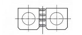
3.2.2 Hinge-connection type
When several rubber fenders are combined together and installed in a line horizontally, the design strength of impingement plates may be increased due to the large space between marine fenders. By use hinge-connection type impingement plates, the marine fenders can also be connected with each other by hinge connection method, thus make the impingement plate system lighter.
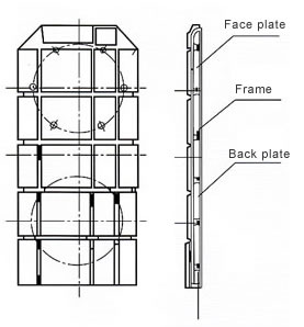
3.2.3 Enclosed type
Enclosed type impingement plate is composed of veneer and back support plate, so as to increase the structure strength. Water pressure test and sealing performance test should be given while manufacturing this type of impingement plate.
3.3 Layout methods for impingement plates

3.3.1 Horizontal installation layout - when the marine rubber fenders are arranged in a line horizontally (like 1×1, 2×1, 3×1, etc.)
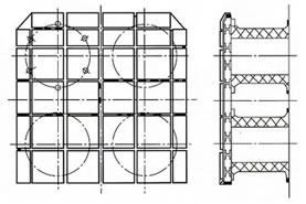
3.3.2 Vertical installation layout – when the marine fenders are arranged in a line vertically (like 1×1, 2×1, 3×1, etc.)
3.3.3 Combinational installation (like 2×2, 2×3, etc.)
4. Veneer
4.1 specification
| Type | Size (L×W) (Thickness: 30mm or 40mm) | ||||
| Flat plate | 600×600 | 600×450 | 600×300 | 450×450 | 300×300 |
| Angle plate | 600×220 | 300×220 | 450×220 | 360×220 | |
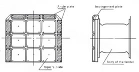
4.2 Material
Both flat plates and angle plates are made using UHMWPE, making them feature high strength and tensile.
| Properties/Materials | PE | Nylon | Rubber (for reference) |
| Specific gravity | 0.95 | 1.15 | 1.15 |
| Stretching strength (Kg/cm2) | 250 | 750 | 200 |
| Tensile stretch (%) | 20 | 50-120 | 450 |
| Compression strength (kg/cm2) | 200 | 900 | 200 |
| Anti-deformation strength (kg/cm2) | 140-210 | 1000 | |
| Young modulus (kg/cm2) | 5600-10500 | 26000 | 40 |
| Shock resistance (kg/cm) | 70 | 200 | |
| Friction coefficient | 0.1-0.2 | 0.2 | 0.3-0.6 |
| Abrasion resistance | 0.5 | 0.28 | 1 |
5. Rubber spring chain
The rubber spring chain refers to a chain designed with rubber springs to reduce forces acting on the chain, thus ensuring safety.
5.1 Composition of the rubber spring chain
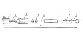
| Series No. | Parts name | Material | Series No. | Parts name | Material |
| 1 | End shackle | Hot dip galvanized Q235 steel | 4 | Common link | Hot dip galvanized Q235 steel |
| 2 | End link | Hot dip galvanized Q235 steel | 5 | Turnbuckle | Hot dip galvanized Q235 steel |
| 3 | Rubber spring frame | Rubber, Hot dip galvanized Q235 steel |
| Specification | Common link | End link | End shackle | Spring frame | Turnbuckle |
| SC630H | Φ20 | Φ22 | M×22 | Φ32 | M36 |
| SC800H | Φ22 | Φ25 | M×25 | Φ32 | M36 |
| SC1000H | Φ25 | Φ28 | M×28 | Φ32 | M36 |
| SC1150H | Φ25 | Φ28 | M×28 | Φ32 | M36 |
| SC1250H | Φ25 | Φ28 | M×28 | Φ32 | M36 |
| SC1450H | Φ28 | Φ30 | M×30 | Φ32 | M36 |
| SC1600H | Φ28 | Φ30 | M×30 | Φ42 | M42 |
| SC1700H | Φ32 | Φ34 | M×34 | Φ42 | M42 |
| SC2000H | Φ34 | Φ36 | M×36 | Φ42 | M48 |
| SC2250H | Φ34 | Φ36 | M×36 | Φ42 | M48 |
| SC2500H | Φ38 | Φ40 | M×38 | Φ52 | M52 |
| SC3000H | Φ40 | Φ42 | M×42 | Φ52 | M56 |
| Specification Weight (kg) Type | 630H | 800H | 1000H | 1150H | 1250H | 1450H | 1600H | 1700H | 2000H | 2250H | 2500H | 3000H |
| P01 | 150 | 460 | 850 | 1140 | 1310 | 1370 | 1630 | 1770 | 2100 | 3050 | 3280 | 4570 |
| P0 | 180 | 560 | 1030 | 1370 | 1570 | 1730 | 2070 | 2660 | 2680 | 3900 | 4330 | 6090 |
| P1 | 235 | 720 | 1340 | 1780 | 2040 | 2380 | 2860 | 3140 | 3730 | 5430 | 6210 | 8820 |
| P2 | 272 | 840 | 1550 | 2050 | 2360 | 2750 | 3220 | 3630 | 4330 | 6430 | 7430 | - |
| P3 | 308 | 950 | 1750 | 2320 | 2670 | 3180 | 3840 | 4220 | 5020 | 7450 | 8680 | - |
Note: When the marine rubber fenders are installed horizontally in a line, the maximum weight of the impingement plate is 80% of the value in above chart.
6. The minimum installation space between supper cell rubber fenders
As the marine fender can be compressed into a drum-shape, there should be a proper space between fenders so as to prevent collision.
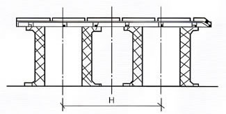
| Specification | 630H | 800H | 1000H | 1150H | 1250H | 1450H | 1600H | 1700H | 2000H | 2250H | 2500H | 3000H |
| H(m/m) | 880 | 1120 | 1500 | 1730 | 1870 | 2180 | 2400 | 2550 | 2880 | 3360 | 3730 | 4500 |
| Angle (degrees) correction factor | 3 | 4 | 5 | 6 | 8 | 10 | 15 |
| Reaction force correction factor (CR) | 0.96 | 0.94 | 0.93 | 0.93 | 0.92 | 0.92 | 0.90 |
| Energy absorption correction factor (CE) | 0.94 | 0.92 | 0.87 | 0.87 | 0.84 | 0.80 | 0.72 |
8. Others 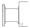 Notes to designers:
As shown in the following diagram, when the anchor bolt is embedded into a concrete structure, the distance between the anchor bolt and the concrete structure surface (L) should be larger than the length of the anchor bolt.
The embedded anchor bolt can also be welded onto the steel frame of the concrete structure, so as to prevent the mooring dolphin from being damaged when the marine rubber fender gets a shearing force or tensile force.
L for different types of supper cell rubber fenders.
| Specification | 630H | 800H | 1000H | 1150H | 1250H | 1450H | 1600H | 1700H | 2000H | 2250H | 2500H | 3000H |
| L (mm) | 330 | 360 | 430 | 500 | 500 | 570 | 570 | 620 | 700 | 700 | 700 | 800 |


